Making a Simple Color Organ

A New Project #
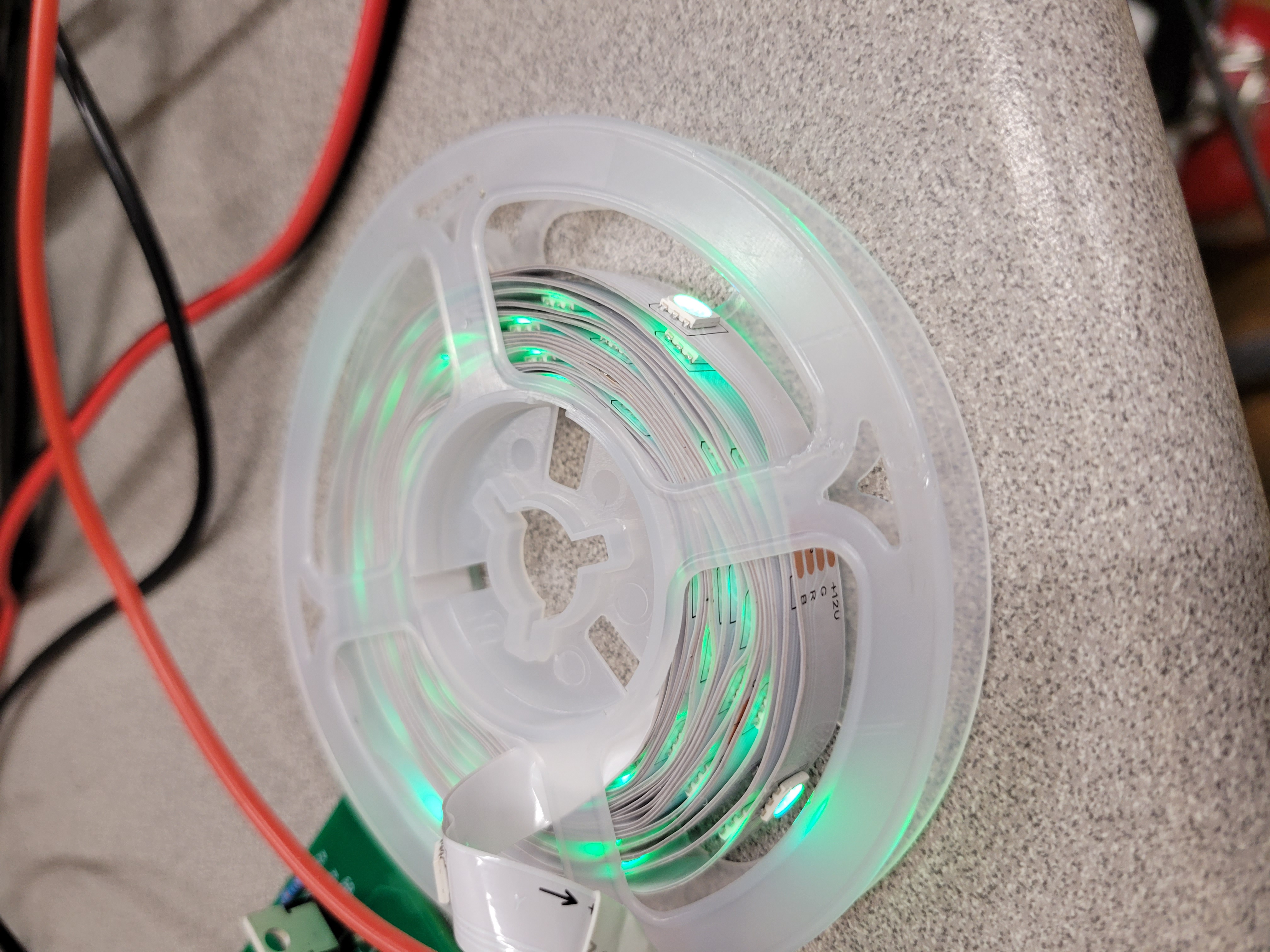
This project was born out of one of my personal hobbies: swing dancing. I was at a dance and my buddy asked me what it would take technologically to control a common RGB light strip with music. I replied that it wouldn’t take very much. I was intrigued by this idea as I was becoming all too familiar with modulating current through LED strings for work. We got to talking about the possibilities and he ended up asking me if I could help him do that. I agreed to give it a shot. I could imagine how cool it would look to have a whole strip of LEDs bob up and down in brightness to the music!
So we then had to get down to brass tacks. What does this thing need to do? Well he replied and said that he wanted different colors to react differently based on the frequency ranges of the music. We settled on individual colors in the strip reacting to bass, treble, and the mid range frequencies. The following was our requirements list:
- It needs to be as simple as possible
- No programming(therefore no microcontroller)
- It needs to work over long distances (from a DJ booth music input to across the dance floor, about 30 ft)
- It needs to be cheap
With those in mind I started thinking about a design
Long Distance #
The biggest problem would be how to simply and cheaply get the audio data from the DJ booth over to the stage where the lights would be. There are all kinds of digital modules out there that can transmit data on different frequencies but it’s hard to manipulate data without a microcontroller. Then it hit me. FM radio! It’s still a very common and cheap way that people use to transmit audio data. I came up with a plan. In the DJ booth, I would use a splitter off the main aux cord and feed that into an FM transmitter. Then at the stage I would receive the signal with a radio. I bought an FM transmitter from Target(they are used for getting phone music to old cars) and used a radio I had lying around to test range. It was a success!
Modulating Current #
Once I could get the audio signal over to where I wanted it, it was time to get to work. I decided that the blue LEDs would correspond to bass, the red to treble and the green to mids. My overall idea was to filter the various bands and to feed them into simple peak detectors. Then, the plan was to use the peak detectors as inputs to linear constant current sources. Let’s go into detail using the most current revision of the design:
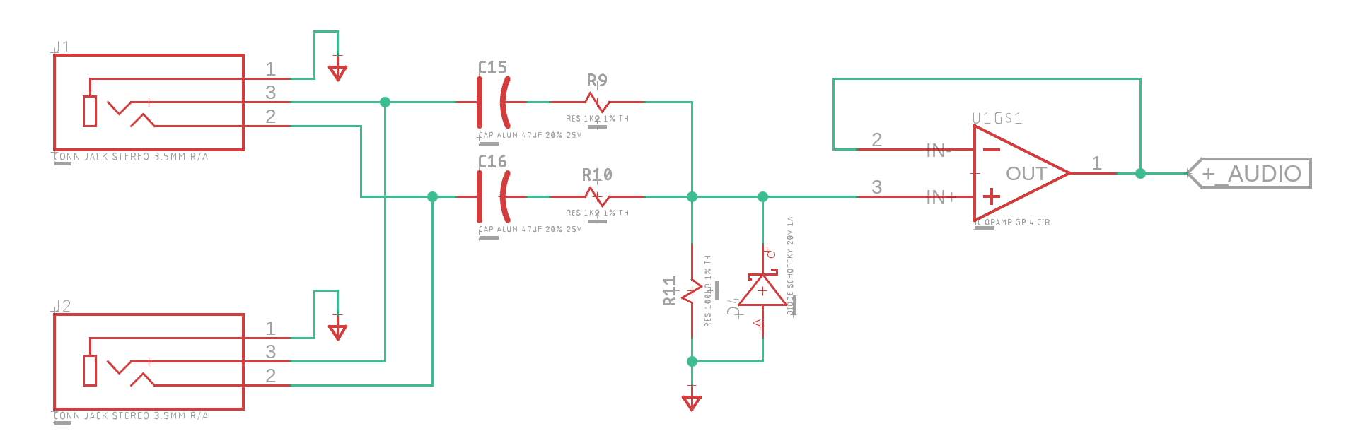
The above is the start of the signal chain. The FM radio’s headphone jack gets connected to J1 to start. The opamp in the above diagram is configured as a voltage follower and will buffer our audio signal. Cleverly, the schottky diode is used to clamp the negative part of the audio signal. We don’t need it. If we don’t use the negative part of the signal, then we don’t need a negative supply rail for any of our opamps. Additionally, we are using the cheap MCP6004 opamp which includes an input common mode range that is slightly below its Vss. This allows us to get away with a signal that has a minimum of -0.2V. The headphone jack J2 is there as a pass through in case the audio needs to be fed to a local amplifier.
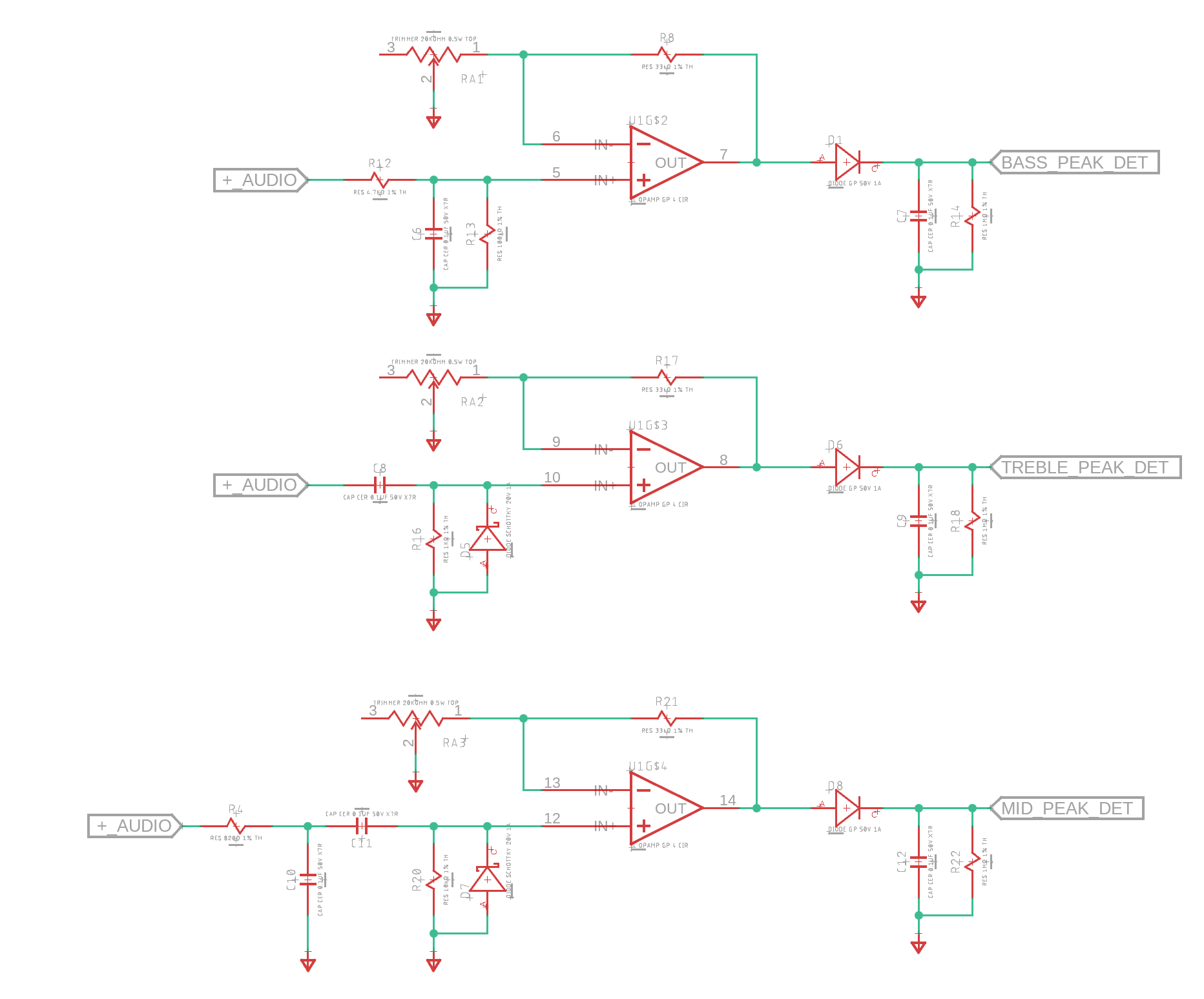
Now our mostly positive, buffered audio gets split through three separate filters-a lowpass,bandpass and a high pass. For configurability, these signals are put through non-inverting amplifiers whose gain is adjustable via potentiometers. Note, that after any high pass filter we need clamping schottky diodes as a high pass filter to remove DC biases.
After the output of the amplifiers, the signals get passed through to simple peak detectors consisting of a diode and a capacitor. Importantly, there is a 1Mohm discharge resistor present. This allows the RGB LEDs to dim as a recovery between notes. The effect would not be as dynamic if the RGB LEDs just held their maximum brightness level the whole song.
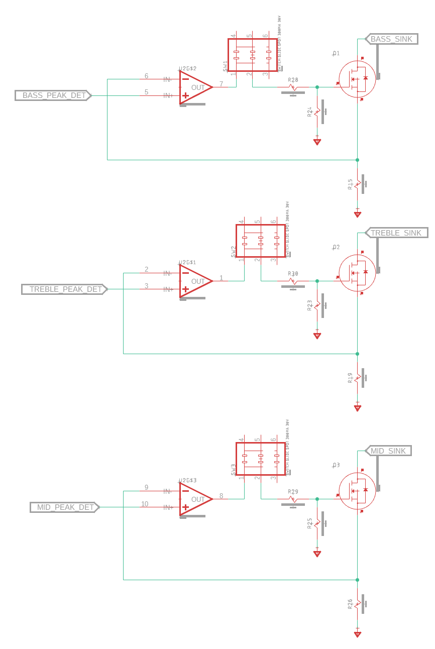
The last step is to feed our peak detector signals into adjustable constant current sources. These sources will sink current proportional to the input peak detector voltage. An example of how the string could be wired is: Bass=Blue, Midrange=Green, and Treble=Red. There are also switches present to turn off the current to individual channels.
A 3D view of the complete board is below:
How Did It Go? #
It went great! My buddy is currently using this design at dances as we speak. The adjustments can be a little fiddly depending on the music volume. However, it meets all the requirements we had. The only disadvantage is that using a linear constant current source is not that power efficient.
For driving longer LED strings I wonder about a design that uses PWM. A PWM based design could be made with or without a microcontroller. The advantage of PWM is that turning the transistors fully on makes them low resistance. This lowers the power loss through the transistor. Additionally, a fully off transistor also has low power losses(none).
Where can I find this? #
All the design files for this Fusion 360 project can be found at https://a360.co/3PgNWKD I hope that this helps all the DJ’s out there with improving the ambiance of their venues!